MAGMASOFT® - A Tool for Faster Decision Making
Godrej Tooling, Mumbai, India, entered the automotive segment 15 years ago as a high pressure die casting toolmaker for what is known in India as the 2-wheeler (motorcycle) industry. However, in the recent past the large number of series production dies needed by the 2-wheeler industry has provided an ideal learning platform for new die makers, resulting in many new companies entering the field.
In order to create a new market for itself, Godrej Tooling decided to address the need for larger die cast-ing dies for automotive applications. The dies for transmission and engine components are large and complex and, being comparatively low in vol-ume, may result in only one die being produced in a year. Successful designs require intense upfront engineering work to ensure that critical areas are properly addressed. The strategy of building up the infrastructure and the design competency for large dies prior to entering into the market worked well for Godrej Tooling. It helped to ensure success on early orders and earned them a positive reputation in the automotive market for large dies.
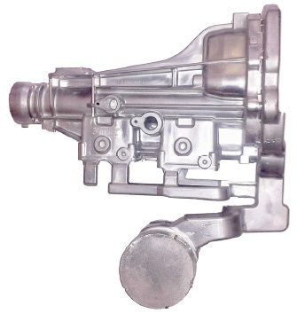
The following case study of one of the early orders showcases the evolution of the design process from the first iteration to the final layout. The entire activity was completed in a crucial two week period of die development, and it ultimately yielded results of 98% of parts meeting the customer‘s acceptability standards on the first test run.
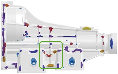
Upon the receipt of the inquiry, an initial solidification analysis was done to verify the castability of the part design and to identify the basic quality issues. In this way, simulation supported the designer at the earliest possible stage, before the design was fixed and while changes could still be incorporated.
During the second stage, initial problem areas were highlighted. Based on the inputs made by the Godrej design engineers, the part design was changed while maintaining the client‘s requirements. At this early stage, simulation played a vital role as communication tool with the customer.
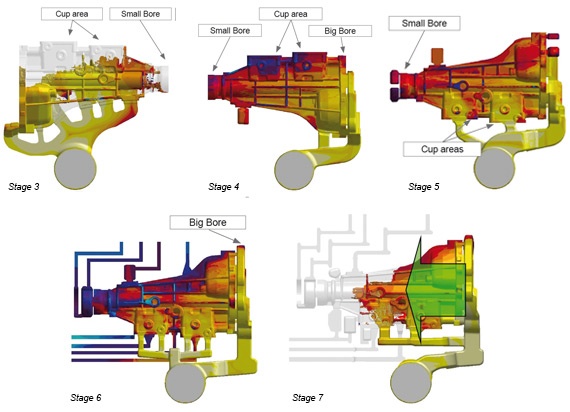
Subsequently, the position of the ingates was determined. A rib running through the entire length of the cast-ing was used as an obvious channel for fast transfer of molten material to the hard-to-fill sections of the casting. The first die filling simulation revealed a non-uniform filling pattern. A reversal of the flow of the metal front was detected at the rib area near the ingate. Further analysis clearly demonstrated an increased danger for air entrapment in the location of the ribs. By studying the complete shot profile, it was seen that a small bore and the adjacent cup filled first before the second cup area got filled.
In the fourth stage, a radical modification of the design was implemented to shift the main feeding location to the big bore flange on the machining face. In addition, one ingate location was retained at the rib to divert the flow towards the cup area. The simulation showed a significant temperature drop in the cup areas and, in addition, a reverse filling was observed in the cup area near the small bore. As a result of this evaluation, further design changes were introduced.
As the overall part orientation was changed, final design improvements such as adding feeding taper in the cup area as well as better overflow design were implemented. The simulation results, however, continued to indicate a drop in metal temperatures at the small bore area, leading to the danger of cold laps or weld lines. All of these issues were addressed in an attempt to improve the shot profile on the HPDC machine.
The final simulations were performed with an improved runner design in the cup area, directly joined to the big bore area. In this way, the problem of melt temperature drop was successfully addressed. Ultimately, the results demonstrated that the joining of metal flow from the cup area with the big bore led to a reduced temperature drop. As a final improvement, a chill vent was added to the runner between the cups to remove the prevailing entrapped air. The problem of weld lines was overcome through a final change of the runner. With the first trial using this tooling configuration, a total of 98% of acceptable parts was achieved.
At Godrej Tooling, MAGMASOFT® validation is now a mandatory process step in the casting die development phase. The benefits of improved yield, reduced reject rate and improved production rate as an outcome of simulation analysis provides a strong competitive edge. The usage of MAGMASOFT® also helped in educating customers about the intricacies of high pressure die casting part design and processes. Today, Godrej’s customers insist on validation through MAGMASOFT® before any decision on product or die changes are taken.
Godrej Tooling, located in Mumbai, India, is part of the $ 3.3 billion Godrej group of businesses, which address a diverse range of consumer and industrial markets in India. Since its inception in 1935, its modern and state-of-the-art facility has evolved into a prominent tool maker for die casting dies, stamping tools and industrial machines. It is well equipped with latest 3-D modelling and MAGMASOFT® software, 39 CNC machines, CNC CMMs and die casting trial machines of 800, 1000 and 2500 ton capacity. With the annual capacity of 300 die casting dies, it is the largest commercial die maker in India. Being an IMS certified company, Godrej has earned a reputation of a “Preferred Die Maker” from OEMs like Honda, Yamaha, Piaggio & Bosch in India.
